Framework Laptop 13 © 2022 by Framework Computer Inc is licensed under CC BY 4.0. To view a copy of this license, visit http://creativecommons.org/licenses/by/4.0/
2D drawings of the Mainboard with the PCB outline, keepouts, and connector locations.
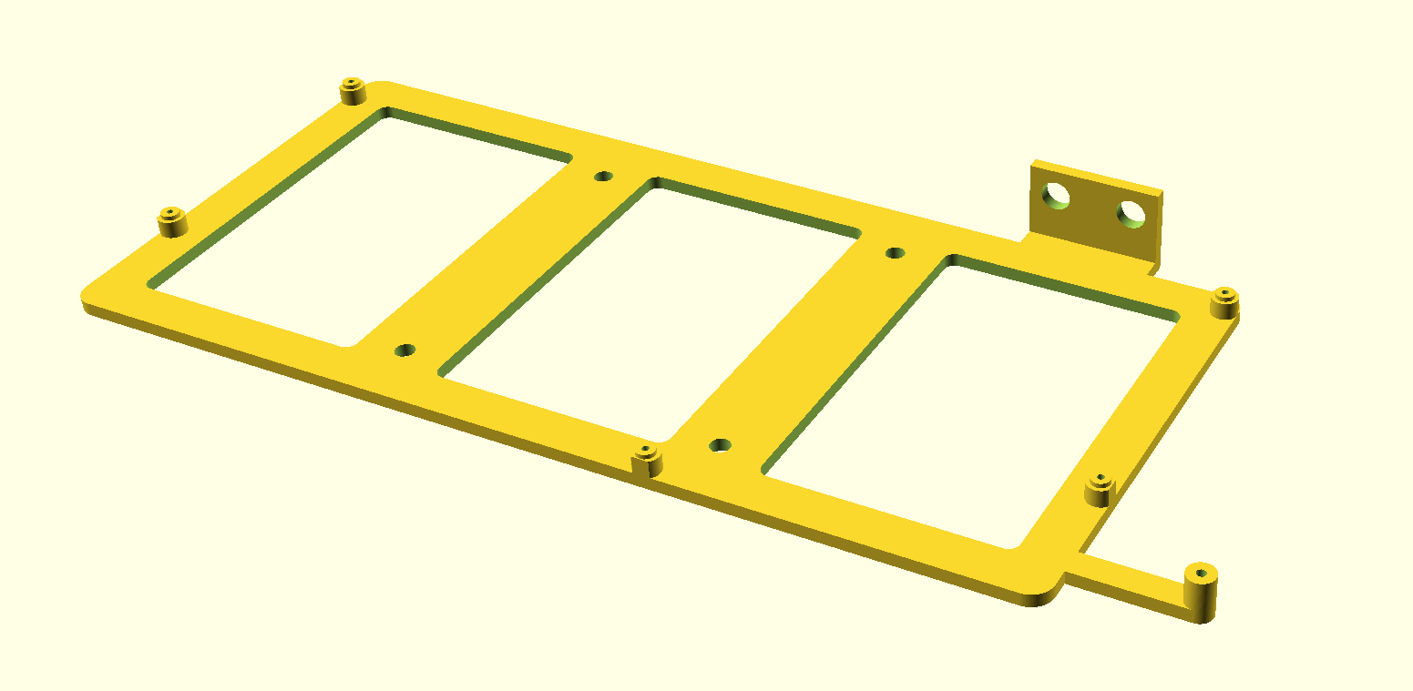
A basic VESA 75mm mountable 3D printable tray modeled in OpenSCAD, usable as a starting point for more complex cases.

A fully featured 3D printable case.
This is a list of connectors on the Framework Laptop Mainboard and the pinouts for them. Note that not all signals listed in each pinout are actually connected on any given version of Mainboard. These are the overarching definitions of the pinouts with some considerations for future generations that may or may not utilize the additional signals.
IPEX 20879-030E connector used to interface to the Webcam Module. Note that the Webcam Module itself currently only uses a 12 pin connector using pins 19 through 30. The remaining signals are not connected.
| Pin | Signal | Type (on Mainboard) | Notes |
|---|---|---|---|
| 1 | GND | ||
| 2 | CSI_0N | Input | MIPI Lane 0 |
| 3 | CSI_0P | Input | MIPI Lane 0 |
| 4 | GND | ||
| 5 | CSI_1N | Input | MIPI Lane 1 |
| 6 | CSI_1P | Input | MIPI Lane 1 |
| 7 | GND | ||
| 8 | CSI_CLKN | Input | MIPI Clock |
| 9 | CSI_CLKP | Input | MIPI Clock |
| 10 | GND | ||
| 11 | SYNC_CAM | Input/Output | Camera FSIN (Frame Sync) |
| 12 | SCL_CAM | Input | |
| 13 | SDA_CAM | Input/Output | |
| 14 | TS_SYNC | Output | Touchscreen frame sync |
| 15 | TS_RST | Output | Touchscreen reset |
| 16 | TS_INT | Input | Touchscreen interrupt |
| 17 | TS_SDA | Input/Output | Touchscreen data |
| 18 | TS_SCL | Output | Touchscreen data |
| 19 | GND | ||
| 20 | USB_DP | Input/Output | Touchscreen or camera USB 2.0 |
| 21 | USB_DM | Input/Output | Touchscreen or camera USB 2.0 |
| 22 | 3V3 | ||
| 23 | CAM_SW | Input | 3v3 |
| 24 | MIC_CLK | Output | 1v8 |
| 25 | MIC_DAT | Input | 1v8 |
| 26 | MIC_SW | Input | 3v3 |
| 27 | INT_ALS | Input | 3v3 |
| 28 | SCL_ALS | Output | 3v3 |
| 29 | SDA_ALS | Input/Output | 3v3 |
| 30 | GND |
IPEX 20879-040E connector used to interface to an eDP display. Note that there are signals defined for both USB 2.0 and I2C touchscreens. There is a PWM interface to control backlight brightness, but the display currently used on the Framework Laptop converts that to a DC LED control. Note that pin 1 is on the left when looking at the receptacle on the Mainboard.
| Pin | Signal | Description |
|---|---|---|
| 1 | BL_POWER | 12-17V backlight power |
| 2 | BL_POWER | |
| 3 | BL_POWER | |
| 4 | NC | |
| 5 | GND | |
| 6 | AUXP | |
| 7 | AUXN | |
| 8 | GND | |
| 9 | EDP_TXP_0 | |
| 10 | EDP_TXN_0 | |
| 11 | GND | |
| 12 | EDP_TXP_1 | |
| 13 | EDP_TXN_1 | |
| 14 | GND | |
| 15 | EDP_TXP_2 | |
| 16 | EDP_TXN_2 | |
| 17 | GND | |
| 18 | EDP_TXP_3 | |
| 19 | EDP_TXN_3 | |
| 20 | GND | |
| 21 | EDP_HPD | hotplug |
| 22 | BLK_PWM_LCD | Backlight PWM |
| 23 | BLK_OFF_N | Backlight Enable |
| 24 | NC | |
| 25 | NC | |
| 26 | 3V_EDP | 3VS |
| 27 | 3V_EDP | |
| 28 | 3V_EDP | |
| 29 | 3V_TS | 3VS for touchscreen |
| 30 | 3V_TS | |
| 31 | USB_DP | USB |
| 32 | USB_DN | |
| 33 | TS_EN | |
| 34 | TS_RST | |
| 35 | TS_INT_N | |
| 36 | TS_SDA | |
| 37 | TS_SCL | |
| 38 | NC | |
| 39 | GND | |
| 40 | GND |
Hefeng AFC42-S15FMA-R3 ZIF connector that goes to the board that has the 3.5mm audio jack as well as the hall effect lid sensor. Note that there are likely other 15 pin ZIF connectors that will work with the FFC we use, but these would be untested.
| Pin | Signal |
|---|---|
| 1 | A_GND |
| 2 | HPOUT_L |
| 3 | HPOUT_R |
| 4 | SLEEVE |
| 5 | SLEEVE |
| 6 | SLEEVE |
| 7 | RING |
| 8 | RING |
| 9 | RING |
| 10 | A_GND |
| 11 | JACK_PLUG |
| 12 | 3V3_HALL |
| 13 | LID_OPEN |
| 14 | BOARD_ID |
| 15 | GND |
Hefeng AWA02-S04FIA-HF connector for the Speakers. Note that there are many other footprint compatible 4-pin connectors that are likely compatible. This kind of connector is also known as "JST SH", and has a 1.0 mm pitch. The same connector is used for the Fan.
| Pin | Signal |
|---|---|
| 1 | SPK_RP |
| 2 | SPK_RN |
| 3 | SPK_LP |
| 4 | SPK_LN |
ACES 50458-01001-001 connector for the Battery.
| Pin | Signal | Notes |
|---|---|---|
| 1 | BAT+ | 24 AWG |
| 2 | BAT+ | 24 AWG |
| 3 | BAT+ | 24 AWG |
| 4 | CLK_SMB | SMBus |
| 5 | DAT_SMB | SMBus |
| 6 | BATT_PRS | |
| 7 | SYS_PRES | |
| 8 | GND | 24 AWG |
| 9 | GND | 24 AWG |
| 10 | GND | 24 AWG |
Amphenol 10156000-051100LF connector for the Input Cover. This includes signals for the Touchpad, Keyboard, and Fingerprint Reader. The mating connector for it is 10156001-051100LF.
Caution: this pinout is Framework schematic-specific, using a symbol with odd-even numbering. It doesn't translate directly to the Amphenol connector footprint numbering - which is counterclockwise. Amphenol connector numbering is shown in the "Conn" column.
| Pin | Conn | Signal | Notes |
|---|---|---|---|
| 1 | 1 | GND | |
| 2 | 50 | KSI0 | Keyboard scanning input 0 |
| 3 | 2 | KSI1 | Keyboard scanning input 1 |
| 4 | 49 | KSI2 | Keyboard scanning input 2 |
| 5 | 3 | KSI3 | Keyboard scanning input 3 |
| 6 | 48 | KSI4 | Keyboard scanning input 4 |
| 7 | 4 | KSI5 | Keyboard scanning input 5 |
| 8 | 47 | KSI6 | Keyboard scanning input 6 |
| 9 | 5 | KSI7 | Keyboard scanning input 7 |
| 10 | 46 | KSO0 | Keyboard scanning output 0 |
| 11 | 6 | KSO1 | Keyboard scanning output 1 |
| 12 | 45 | KSO2 | Keyboard scanning output 2 |
| 13 | 7 | KSO3 | Keyboard scanning output 3 |
| 14 | 44 | KSO4 | Keyboard scanning output 4 |
| 15 | 8 | KSO5 | Keyboard scanning output 5 |
| 16 | 43 | KSO6 | Keyboard scanning output 6 |
| 17 | 9 | KSO7 | Keyboard scanning output 7 |
| 18 | 42 | KSO8 | Keyboard scanning output 8 |
| 19 | 10 | KSO9 | Keyboard scanning output 9 |
| 20 | 41 | KSO10 | Keyboard scanning output 10 |
| 21 | 11 | KSO11 | Keyboard scanning output 11 |
| 22 | 40 | KSO12 | Keyboard scanning output 12 |
| 23 | 12 | KSO13 | Keyboard scanning output 13 |
| 24 | 39 | KSO14 | Keyboard scanning output 14 |
| 25 | 13 | KSO15 | Keyboard scanning output 15 |
| 26 | 38 | GND | |
| 27 | 14 | CAPS_P | +5VS through 1.33k resistor |
| 28 | 37 | CAPS_N | Low-side control by the EC |
| 29 | 15 | GND | |
| 30 | 36 | KBL_P | High-side 5V PWM by the EC |
| 31 | 16 | GND | |
| 32 | 35 | KBL_P | Same as 30 - see [1] |
| 33 | 17 | GND | |
| 34 | 34 | TP_SCL | Touchpad I2C SCL |
| 35 | 18 | TP_INT | Touchpad interrupt GPIO |
| 36 | 33 | TP_SDA | Touchpad I2C SDA |
| 37 | 19 | TP_BOARD_ID | |
| 38 | 32 | 5VS | 5V, touchpad - see [2] |
| 39 | 20 | 5VALW | 5V, fingerprint, see [3] |
| 40 | 31 | USB_DM | Fingerprint sensor USB |
| 41 | 21 | GND | |
| 42 | 30 | USB_DP | Fingerprint sensor USB |
| 43 | 22 | FPR_CTRL | See [4] |
| 44 | 29 | SWITCH | Power button pin |
| 45 | 23 | FPR_LED_W | See [5] |
| 46 | 28 | FPR_LED_R | See [5] |
| 47 | 24 | FPR_LED_G | See [5] |
| 48 | 27 | FPR_LED_COM | 5V, fingerprint LED, see [3] |
| 49 | 25 | GND | |
| 50 | 26 | NC |
- [1] The connector has two KBL_P pins - in order to increase current capacity. They're created from +5VS rail.
- [2] Connected to the +5VS (switched) rail through a 0 ohm resistor
- [3] Connected to the +5VALW (always-on) rail through a 0 ohm resistor
- [4] FPR_CTRL is used to filter out power button presses while the fingerprint sensor is scanning
- [5] The EC drives these LED's through low-side transistors. The RGB channels from the EC drive the white, green, and red fingerprint LED's, respectively.
Hefeng AWA02-S04FIA-HF connector for the Fan. Note that there are many other footprint compatible 4-pin connectors that are likely compatible. This kind of connector is also known as "JST SH", and has a 1.0 mm pitch. The same connector is used for the Speakers.
| Pin | Signal |
|---|---|
| 1 | 5V |
| 2 | FAN_SPEED |
| 3 | FAN_PWM |
| 4 | GND |
NOTE: The mainboard will charge this battery, so a rechargable ML1220 battery MUST be used. For example, CR2032 MUST NOT be used, it cannot be charged and will likely be damaged.
RTC battery is used for storing persistent but resettable information. This includes the time and DRAM training. Disconnection will result in deletion of that information. If no battery is connection, DRAM training needs to happen on every boot, slowing down the boot process significantly.
Framework 13 Intel Core 11th through 13th Generation use an onboard coin cell battery as RTC.
We use the Lotes LOTES_AAA-BAT-046-K01 connector.
On AMD Platforms and starting with Framework 13 Intel Core Ultra Series 1, no RTC battery is included anymore. Settings are kept alive by the normal system battery. The only case where an RTC battery is recommended, is when the system is used in standalone mode (without a battery).
Cvilux CVILU_CI4402M1HRC-NH connector for the RTC Battery.
| Pin | Signal | Location |
|---|---|---|
| 1 | +RTCBATT | Left |
| 2 | GND | Right |